Dough Proofing Boxes
Overview
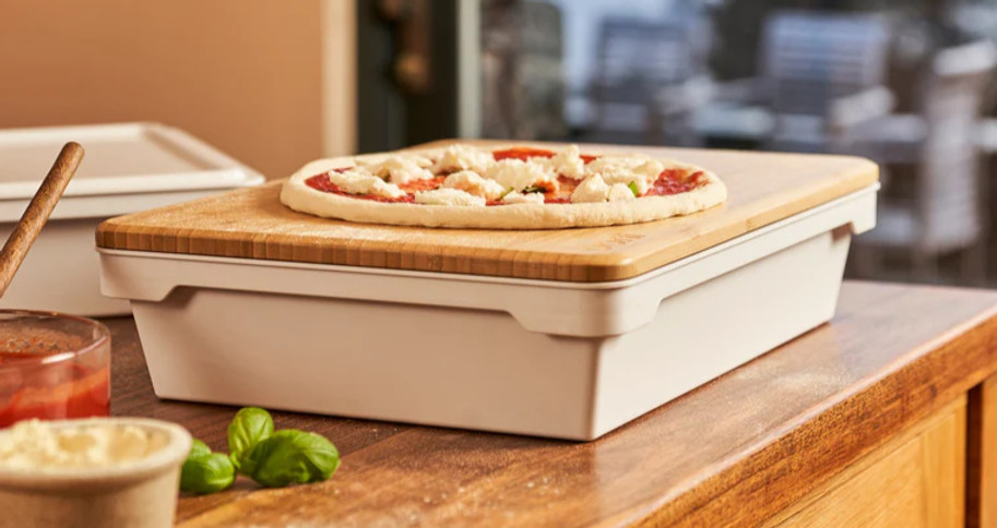
At first glance, this is a simple product. A plastic tray designed to proof dough balls in. This is exactly the feeling that I wanted the end user to experience: Something that just works. If the user were to say: 'I wonder why they did that', or 'this feature is super clever', the understated design intent would have failed. The idea was effortless function no matter what the user tries to do with it. To make this invisible experience for the user requires much complex design thought.
Behind that design sat a tightly constrained architectural problem spanning:
-
Internal volumetric efficiency
-
Regional fridge envelope limits (UK / EU / US)
-
Draft-dependent nesting geometry
-
Structural stiffness, and consistent results in large-format injection moulding
-
Dimensional tolerance across multiple interacting states
-
Tooling cost sensitivity and scrap risk
As my first design engineering product, this project has a special place in my heart as it became foundational in shaping how I approach product development: define the architectural hierarchy early, make constraint interaction explicit, and reduce downstream manufacturing risk before committing to steel. This methodology pays off exponentially the more complex a project is.
Feasibility and Exploration
The trays were required to:
-
Accommodate six 250g dough balls
-
Be tall enough to bulk proof one 1.5 kg dough ball
-
Nest to minimise volume when stored
-
Fit within common domestic refrigerator depth and shelf spacing constraints across multiple regions
-
Maintain a smooth, hygienic interior with not features making it hard to remove dough
-
Stack securely with and without lids
-
Pass certification needed to sell food safe products
-
Be easily manufacturable as large-format injection moulded components at commercial volumes
These requirements were not only pulling the design in multiple different directions, they were sometimes exactly contradictory:
Increasing base size reduced allowable draft to still fit in a fridge
Reducing draft limited nesting ability.
External footprint limits constrained wall strategy.
Stiffening features introduced sink, cooling considerations and opposed the clean internals requirement
Tolerance strategy influenced stacking stability and scrap probability.
All of these are bound by injection moulding efficiency consideration for example no side-actions allowed and one injection point allowed for each part.
Adjusting one parameter shifted the behaviour of the entire assembly and had cascading influence on all of the other requirements.


At project outset, stakeholder priorities differed. Some preferred capacity, some wanted to reduce space taken up when stored, clean internal geometry was a non-negotiable for others and of course, cost and manufacturability were critical.
With all of these opposing opinions, rather than iterating geometry reactively depending on the loudest voice at that time, I formalised the constraints into a structured model that mapped how:
-
Draft angle
-
Internal volume
-
External envelope
-
Stack interface geometry
-
Wall thickness
-
Rib strategy
interacted as a system.
I then produced multiple design proposals which prioritised different aspects but without failing other requirements. When I presented this to the stakeholders, it was easy to visualise exactly how each of their priorities affected the others'.
This reframed decision-making from preference-based debate to structured trade-off analysis. A decision was made there without the need for costly prototypes to find out something that could be thought through in advance.


Product Development and Detail Design
After the feasibility study and design direction stage, the stakeholders agreed on approach b as the best design approach. This meant that we could move from more conceptual design work to more detailed product development.
Being so constrained by requirements can be a blessing as well as a curse since the product almost designs itself. The base is determined by the doughball sizes, the internal height by the bulk proofing height balanced with storage, draft to be as large as possible to aid nesting.
I knew I wanted it to have a minimalist feel which worked well with the requirement to keep the inside featureless and clean. For Injection moulding this means the outside has the same qualities.
Even with the tight design constraints, there was still plenty of design work to be done. After a little basic prototyping work, I decided that small internal radii would make it easier to remove dough since dough-tools are generally stiff and can't bend around a large radius to effectively separate the dough from the tray. The handle geometry was added for the second tray to have somewhere to sit when nested which also had the benefit of stiffening the tray.
Design concept B meant the lower rib was added to the corners so that the second tray would sit high enough not to bind when nested inside the lower tray. It was also useful at giving an area underneath the upper handle for the user to separate the trays easily. With this in mind, it was placed just in the corners and designed to look like handle features. The lid was given a joggle to stiffen it as a large flat part. The inside of the joggle nicely holds the lower tray base geometry and the outside is designed to sit just inside the assembly rib of the other lid so the upper lid doesn't slide around when stored on top. A healthy dose of radii fiddling to give a concentric look despite the drafted design and some finishing touches later, the drafted design was completed.
Rapid prototyping is always incredibly useful when nailing down design decisions such as the handle overhang size, the fit of tray in tray, and how a tray might look with the prep lid on: see images below.
From here, detailed DFM work, as always, made every aspect 10x more complicated. Split line, Draft on the ribs and wall thickness considerations made the perfect solution physically impossible (without super-complicated tooling which was off the table.) In the end compromised has to be made justified by their effect on the end result. These include minor sink marks being accepted around the corner flanges, non-concentric radii and other minor trade-offs.
Overall, however, I was pleased with the design and think it fits the minimalist look that I was going for and perfectly complementing the prep lid.


Preparation for Manufacture
The most commercially sensitive risk was dimensional behaviour across multiple functional states due to manufacturing tolerances:
-
Tray + lid
-
Tray nested within tray
-
Tray + lid+ second tray
-
lid on lid
Because trays and lids were produced in parallel tooling, dimensional variation could not be considered in isolation.
Using configurable CAD boundary models, I evaluated upper and lower tolerance conditions to understand stack-up propagation through each state. Particular attention was given to lid fit on trays and nested fit. With draft on the lower flange and tooling direction considered, tolerances presented cases where the nested trays slipped off each other and jammed, lids were too loose or too tight.
Assuming a bell-curve distribution of tolerances around the nominal, I aimed to minimise failures to less than 1%. To achieve this, compromises had to be made and minor sink was accepted due to thickening rib geometry rather than nominal wall thickness. The latter solution would increase material use driving costs and reducing sustainability of design. It would also require a larger hold-time for cooling of the plastic driving cycle times higher which is a hidden cost that must always be considered when designing for large volumes.
This probabilistic framing significantly reduced commercial risk and reduced scrap rate, something else that is important when trying to design sustainably.


As a large, relatively flat moulding, the parts carried inherent risks such as warpage from uneven cooling, sink from wall meeting points, cycle time sensitivity. On top of that, the large steel tools cost so much that it is critical to get it right on the first try and ensure the design is steel safe.
Thin ribs under the handle flanges was integrated to provide stacking load transfer and global stiffness. The rib depth and intersection thickness were tuned to manage sink visibility while maintaining structural performance and maintaining low scrappage due to tolerance rates.
The lid geometry incorporated embossed features to increase bending stiffness without increasing nominal thickness, controlling mass and shrink behaviour.
Following this dfm stage, I produced fully dimensioned engineering drawings highlighting critical interfaces and collaborated with the UK manufacturing partner in a structured DFM review prior to tool steel release.
Early constraint modelling reduced the likelihood of late-stage tool modification which is a significant commercial exposure in injection moulded products of this scale. This is why I always like to start projects that way where possible.

Outcome and Reflection
The design highlights include:
-
Stable stacking across multiple configurations
-
Reliable nesting for easy storage
-
Regional fridge and cupboard capability with ample dough capacity both bulk and balled
-
Reduced scrap risk through architectural robustness and controlled tolerances
-
Easy and intuitive user interaction
-
Clean, minimalist look fitting in most kitchen styles
The product has been sold by Ooni for over 3 years so far and maintains consistently strong customer ratings, reflecting durability and usability in real-world conditions.
To the end user, it remains a straightforward tray system with the architectural complexity intentionally invisible.

This project taught me some incredibly valuable lessons:
1. Small geometric decisions propagate across all aspects of a product. Add in manufacturing consideration and tolerance behaviour and changes that are assumed to be minor can skyrocket commercial risk. This is why it is essential to map architecture early, evaluate feasibility early and consider manufacture of parts throughout the entire design process.
2. Nailing down requirements and their relative importance is crucial for evaluating design decisions later and although this process is often brushed over, it needs a real deep dive and engineering style feasibility study before committing to costly product development that, without this process, is likely to turn into reactive, fire-fighting.
3. Compromise is necessary in product development. Often, even with the cleverest solutions, satisfying every requirement and desire is impossible. Knowing where to compromise and where to prioritise is essential. Always zoom out and see the effect of one decision on all of those around it and the system as a whole.
I think they can be summed up in an approach that I have taken into my engineering career:
Zoom out early: Clarifying architectural hierarchy and constraint interaction early is cheaper than resolving conflict after tooling commitment.
With hindsight, earlier integration of supplier process capability data (Cp/Cpk) may have enabled looser probabilistic optimisation of stacking behaviour and reduced the need for the cosmetic trade-offs. This is something that I would do differently if I was to do this project now with more experience.